Steps to Build an Effective Network Diagram:
Network diagrams play a crucial role in understanding and visualizing the intricate web of connections that make up a computer network. Whether you are managing a small office network or a complex enterprise infrastructure, constructing a clear and purposeful network diagram is essential for effective communication, troubleshooting, and planning. In this article, we will explore the steps to build an effective network diagram.
Understanding the Purpose:
Before embarking on the journey of creating a network diagram, it is crucial to establish a clear purpose. A well-defined purpose guides the creation process, ensuring that the resulting diagram serves its intended function. Whether the goal is to document an existing network, plan an expansion, or troubleshoot connectivity issues, having a purpose in mind will shape the structure and content of the diagram.
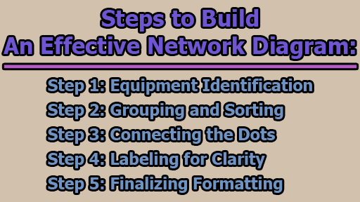
Step 1: Equipment Identification: The foundation of any network diagram lies in the identification of the network’s components. Begin by compiling a comprehensive list of all the equipment that constitutes the network. This includes workstations, servers, routers, switches, firewalls, and any other devices that play a role in the network infrastructure.
If you are utilizing network diagramming software, leverage its capabilities by dragging and dropping shapes that represent each network component onto the canvas. Resist the urge to focus on connections at this stage; the primary goal is to create an exhaustive list of equipment.
Step 2: Grouping and Sorting: With the list of equipment in hand, the next step involves grouping and sorting the shapes based on logical relationships or physical proximity. Grouping related components together enhances the clarity and organization of the network diagram. Depending on the context and purpose, shapes may be grouped by function, location, or any other relevant criteria.
For instance, consider grouping workstations in one area and servers in another. Alternatively, organize devices based on their roles within the network, such as separating core networking components from end-user devices. This step sets the stage for a more organized and coherent representation of the network’s structure.
Step 3: Connecting the Dots: Having grouped the shapes, it’s time to establish the connections between them. The lines connecting the shapes on the diagram represent the various links and relationships between network components. These connections may denote physical wiring, data transfer paths, or any other relevant interactions.
Pay close attention to the logical and physical layout of the network when creating connections. Ensure that the lines accurately reflect the actual relationships between devices. For instance, a line between a workstation and a server might indicate a direct communication path, while a line connecting two switches signifies the interconnection of network segments.
Step 4: Labeling for Clarity: To enhance the comprehensibility of the network diagram, incorporate labels for each shape with additional information that aids understanding. This information may include device names, IP addresses, or any other relevant details. Clear labeling ensures that anyone reviewing the diagram can quickly grasp the key information without ambiguity.
Alternatively, consider numbering each component and creating a legend that provides detailed information about each numbered item. This approach streamlines the visual representation, preventing clutter and making the diagram more accessible to a diverse audience.
Step 5: Finalizing Formatting: The final step involves refining the aesthetics of the network diagram to ensure clarity and visual appeal. Adjust the size, color, and other properties of diagram elements to improve readability. Consistency in formatting is crucial; use uniform colors and styles to maintain a cohesive visual language throughout the diagram.
Consider using different colors to distinguish between various groups of components or to highlight critical elements within the network. By investing time in the final formatting, you not only enhance the diagram’s visual appeal but also contribute to its effectiveness as a communication and documentation tool.
Best Practices and Additional Considerations:
While the above steps provide a foundational guide to constructing a network diagram, several best practices and additional considerations can further refine the process:
- Documenting Port Numbers and Protocols: Include information about port numbers and protocols associated with each connection, offering a more granular understanding of data flows within the network.
- Version Control: Implement version control mechanisms to track changes made to the network diagram over time. This ensures that the diagram remains an accurate reflection of the network’s current state.
- Use of Symbols: Utilize standardized symbols for common network components, such as servers, routers, and switches. Consistency in symbol usage enhances the diagram’s professional appearance and clarity.
- Consideration of Future Scalability: Anticipate future changes and scalability requirements when constructing the network diagram. Leave room for additions and modifications to accommodate the network’s evolving nature.
- Collaboration and Documentation: Foster collaboration by involving relevant stakeholders in the creation and review of the network diagram. Additionally, maintain comprehensive documentation alongside the diagram to provide context and details for reference.
- Regular Updates: Treat the network diagram as a living document that requires regular updates. As the network evolves, ensure that the diagram reflects the most current state of the infrastructure.
In conclusion, constructing a network diagram is a systematic process that involves careful planning, organization, and attention to detail. By following above step-by-step guidelines, you can create a beautiful and usable network diagram that serves its purpose effectively. Remember, it’s often more beneficial to create multiple diagrams, each highlighting a distinct aspect of the network, rather than attempting to incorporate everything into a single, cluttered representation.

Assistant Teacher at Zinzira Pir Mohammad Pilot School and College


